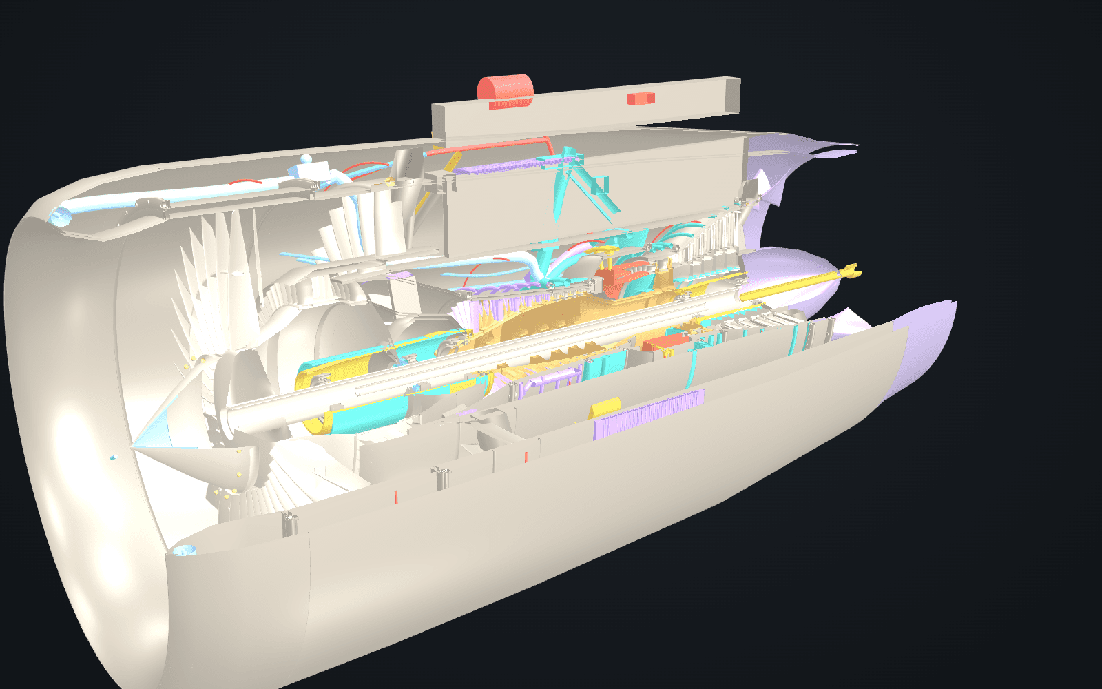
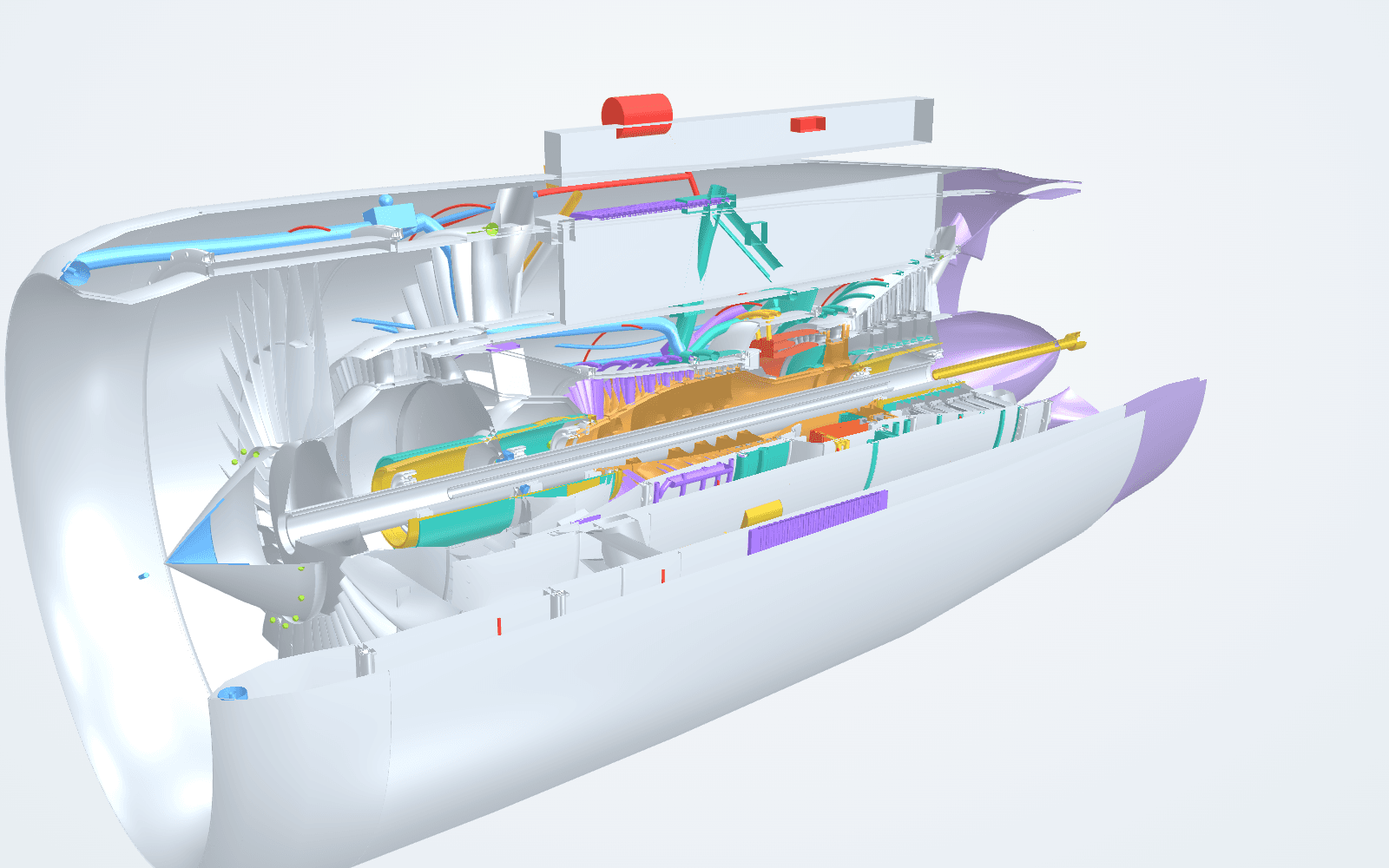
Wrote two CadQuery generators that size a design before they draw it: a flight-control actuator family across four aircraft classes, and an engine accessory gearbox family across five power ratings. Changing one input — bore, or shaft power — propagates through gear sizing, bearing selection, housing geometry and the bill of materials, whose masses come from the generated solids' own volumes rather than a separate estimate.
Sized the gearbox from the Lewis bending equation solved for module, then snapped that module up to a standard cutter size — so the safety factor is a consequence of the preferred-number list rather than a figure anyone chose. Tooth flanks are true involutes of the base circle; bearings are real SKF 60xx-series parts picked on shaft torque.
Took the actuator from geometry to a releasable drawing pack: four A4 sheets carrying ISO 286 limits and fits (⌀ 35 H8 bore, ⌀ 21 f7 rod), ISO 1101 geometric tolerances on the features that decide function — cylindricity on the bore rather than roundness, total runout rather than concentricity, position at maximum material condition on clearance holes — a chosen datum scheme, surface finishes, and a five-contributor tolerance stack on installed length reported both worst-case and RSS. The tolerances are derived from the model, not typed onto it, and a test asserts the stack's nominal equals where the assembly actually puts the clevis.
Added a formed sheet-metal bracket, because a folded part is a different discipline from a machined one: the blank a shop cuts is shorter than the finished part's legs added together, by one bend deduction per fold. Bend allowance from a K-factor neutral axis, five design-for-manufacture rules — minimum bend radius, flange length, hole-to-bend distance, fastener edge distance — and a material trade with a real answer: 2024-T3 is twice as strong as 5052-H32 and cannot make the fold, because its minimum bend radius is 4T against 1T. Validated by conservation of volume: forming moves metal without creating it, so the blank and the formed solid agree to 0.25%, against 5.12% for a naively summed blank.
Then loaded that bracket and found it fails — 2 kg of avionics at a 9g crash factor, solved with CalculiX through FreeCAD headlessly. The result worth having was not the stress but the mesh study: refining from 173k to 333k nodes, deflection converged to 0.06% and bulk stress to 0.28%, while the peak stress climbed 12% and never settled. Its location says why — every peak node sat at z = 0.00 exactly, on the bore edge of a constrained hole, hopping between the two holes run to run. A fixed constraint is singular at its own boundary, so that 545 MPa peak is a boundary condition rather than a stress, and refining further would only make it larger. The converged answer is 196.7 MPa against a 193 MPa yield: the part is marginal, not catastrophic, and the difference between those two verdicts is the whole reason to refine a mesh more than once.
Then closed the loop: screened four ways of fixing the bracket by hand before modelling any of them, because ruling a candidate out with a section modulus costs seconds and building then solving it costs hours. The instructive result was the option that looked best. Folding the upright's free edges into flanges makes that leg 7.4× stiffer — 235 down to 32 MPa — and changes the bracket's margin by nothing at all, because both legs carry the same moment through the same section and the governing stress simply moves to the untouched base. It costs 14% more mass and fails at exactly the same load. Chose 2.0 mm gauge instead, the lightest arm that passes, and treated it as a drawing re-issue rather than an edit: the bend deduction changes, so the blank goes 101.52 to 100.97 mm and a shop cutting to the old sheet would make the wrong blank.
Solved the chosen redesign to confirm it: 126.1 MPa converged against a 193 MPa yield, a +53% margin where the original had −2%, and deflection halved from 4.83 to 2.46 mm. The peak still diverges in exactly the same place, which is the right answer — the singularity belongs to the constraint, not the part, so a thicker part should not cure it. Only the winner was solved, and that is defensible because the beam model reads 16% high at both gauges, agreeing to 0.2 of a point across a 25% thickness change; a test pins that calibration, because if it drifts the screen has stopped being safe.
Backed that solver result with closed-form beam theory sharing none of its code, which put the nominal at 235 MPa — also past yield, from a different direction — and surfaced what a single-cantilever idealisation misses: most of the tip movement is the base rotating, not the upright bending, because the base reacts the moment back to the bolts through the same 1.6 mm of material. A test pins the non-convergence itself, so if anyone later rounds that edge and the peak starts converging, the suite fails and the claim gets rewritten.
Sized a bleed-air duct from station 3 of my own turbofan cycle model — 759.5 K at 12.5 bar — and routed it in pyOCC as a solid swept along a 3D spline, then measured true minimum distance to the structure around it. Two findings the arithmetic gave up rather than the drawing: the wall is governed by surviving a 2× diameter bend, not by hoop stress, because bending thins the outside by 20%; and the clearance requirement is 10.5 mm because stainless at 760 K grows 7.6 mm over a metre before anything vibrates. The obvious short route fouled the casing outright, and it is kept in the repository beside the one that works.
Wrote a design-for-manufacture checker that reads a STEP file it did not create — wall thickness by firing rays through the solid, draft from face normals, hole aspect and internal corner radius from the cylinders that are holes rather than fillets. Run across every part in the repository it found seventeen failures on the gearbox housing as a casting, which that project's own README lists as a known omission: the checker recovered it from the geometry, having never read the README. Its ray-cast wall thickness also returns 3.00 mm on the actuator, exactly the wall_thickness constant its generator sets, by a path that shares no code.
Wrote 78 tests for the gearbox generator — the last of the five with none, and the one with the most defects already found, which is not a coincidence. They found another: both tooth profiles are drawn with a tooth centred on their own +X axis, so with an even gear the two solids overlapped by 424 mm³, 2.1% of the pinion, in every exported assembly. Every member of the family has an even gear. Fixed by phasing the gear half a tooth pitch, and the parity matters — an odd gear already presents a gap, so rotating it causes exactly the clash it avoids. Both directions are pinned by tests and the STEP files are regenerated.
Checked those tests by reintroducing the original involute sign error to confirm the suite goes red. It does, but through only one test of the three that look like they should catch it. Tooth thickness at the pitch circle is still correct with the sign mirrored, which is why the bug survived its first review; and BRepCheck_Analyzer validity still passes too, because at every tooth count this project ships the mirrored flanks stay inside their own sector and the solid is genuinely well-formed. Only checking that the tooth narrows from root to tip finds it. Verifying geometry is well-formed is a different question from verifying it is right.
Checked the geometry rather than assuming it, which is what found the interesting problems: the involute half-angle carried the wrong sign, giving hourglass teeth whose flanks crossed and a solid that failed BRepCheck_Analyzer and would not triangulate; the housing footprint was driven by bearing-boss diameter, so the 50 kW gear hung 84 mm outside its own casing; the actuator assembly stacked every part at the origin, sealing the rod and its rod-end inside the barrel; the clevis was too small to carry its own bolt holes clear of its pin bore; and every BOM mass was a hand-rolled formula, one of them wrong by 5.3×. All fixed, all covered by tests.
Python · CadQuery · pyOCC · GD&T · ISO 286 · ISO 1101 · Sheet metal · DFM · FEA · CalculiX · STEP